")
")

Axial fan & centrifugal fan connection with protection technology
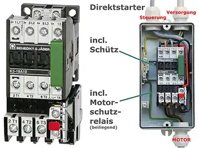
The connection of a Kaiser axial fan or radial fan with motor protection switch and contactor
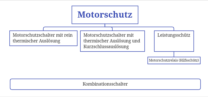
A motor protection switch is used to protect electric motors and is installed in front of them in the circuit. There are different types:
1. The motor protection switch with thermal release (bimetal)
2. The motor protection switch with thermal and electromagnetic release, which also ensures protection against short circuits.
3. The power contactor, usually in conjunction with an auxiliary contactor
4. The auxiliary contactor (motor protection relay) for the thermal contact sensor TK in the motor as a supplement to the motor protection switch.
A combination of all of the above
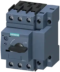
- Motor protection switch with thermal release
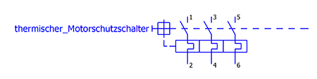
A thermal release (a bimetal) is built into the motor protection switch, which is set to the rated motor current. This release protects the motor from overload if more than the set rated motor current flows through the cable for a long time. A bimetal consists of two metals pressed together. Both have a different coefficient of thermal expansion. The thermal or linear expansion coefficient indicates the expansion when the temperature increases by 1 K. If the bimetal is heated, it begins to bend.
The heating of the bimetal causes a deformation that, at a certain point, breaks the conductive connection (triggers the switch lock), which leads to the supply voltage being switched off.
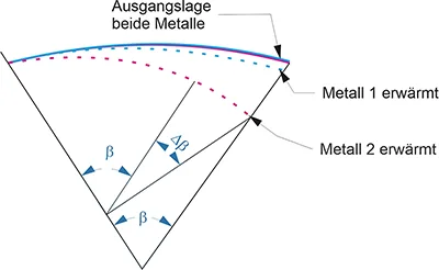
When the device cools down, the bimetal restores the conduction. In the case of a motor protection switch or power contactor (see below), automatic reactivation must therefore be prevented and the device must be reset manually.
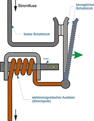
- Electromagnetic release:
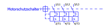
If a short circuit occurs in the winding of the motor, a magnetic field is generated by a current coil in the motor circuit breaker.
armature is drawn into the coil and collides with the movable switching element. This opens the contacts and safely shuts off the short circuit.
As a switching lock (not visible here) is opened at the same time, the circuit breaker remains in the secured "OFF" position after the short-circuit switch-off and must be reset manually after checking the fault.
- Power contactor and auxiliary contactor:
A contactor is an electromechanically operated switch. A control current flows through a magnetic coil, whereby the resulting magnetic field pulls the contacts into the active switching position (closed). If no current flows, a return spring restores the initial state (open). Contactors are constructed almost identically to relays.
Contactors can be divided into power contactors and auxiliary contactors. These are differentiated based on the power they can switch.
Auxiliary contactors are also known as motor protection relays, which describes the way they work better.
A power contactor can switch power from 500W to several hundred kilowatts. Auxiliary contactors (motor protection relays) are more likely to be placed in the relay power range and are used to control power contactors. They can be used in combination with power contactors, e.g. to use control voltages with direct current DC in the auxiliary contactor and to control power voltages with alternating voltages AC in the motor switch, since the control circuit and the currents to be switched are isolated from each other.
But there are also ready-made combinations that correspond to extended power contactors.
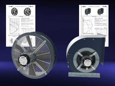
Connection of Kaiser axial fans & centrifugal fans
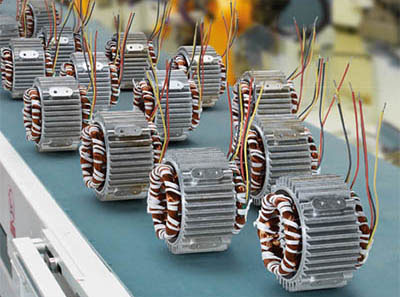
Bimetal switches are installed in Kaiser fan motors (except small motors). See above for function.
These bimetal switches can be operated with 230 volts, which allows the use of simpler contactors or ready-made combined motor protection switches with the appropriate connection.
Thermal sensors or bimetal switches are embedded in the winding head of the motor. This allows the temperature to be monitored efficiently and independently.
The high-performance bimetal switches do not require a tripping device, as they are automatically reset after cooling down. This means that they can be integrated into the phase line of AC motors.
Due to the independent switching function, a thermal sensor is a very reliable and particularly cost-effective option for modern temperature monitoring and limitation. The bimetal disk of the thermal sensors used is dimensioned in such a way that when a predefined and fixed temperature value is reached, it is moved vertically away from the contact plate in a fraction of a second and the contact is opened.
However, for three-phase motors (3~ motors), a contactor is required so that all poles (all three lines L1, L2, L3) can be switched off. The use of 3 thermal sensors (one for each phase) would theoretically be possible, but would not always lead to all-pole disconnection if the motor experienced different cooling. Then only 1 or 2 bimetals could trigger and not all 3 at the same time.
This combination is available from various manufacturers for installation in control cabinets or ready in its own housing including a switch.
Examples:
Example of the simple combination of circuit breaker and thermal contact switch (bimetal) for 3 ~ motors.
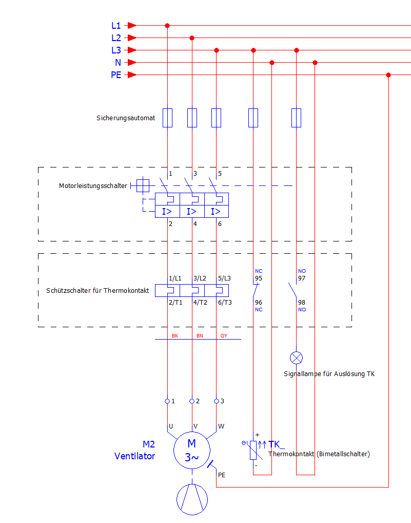
Complete system of bimetal connection:
If you have any questions do not hesitate to contact us.
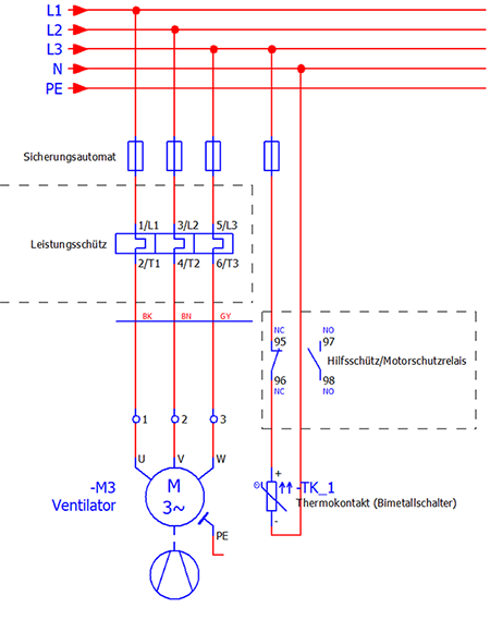
Contact designations:
The contact designations are standardized and mean:
• 1,3,5 are the power inputs for the high voltage lines (230V or 400V)
• 2,4,6 are the outputs of the current-carrying lines.
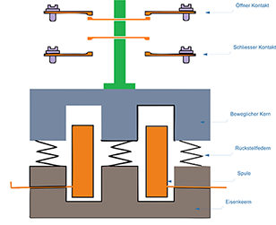
• Auxiliary contacts have two digits if they have a special function, in the case of contactors they have the function of opener and closer and have the numbers 5-6 or 7-8 in the second digit. In addition, the letter combinations "NO" and "NC" are often printed, the meaning of which is derived from NO for "Normally Open" and NC "Normally Closed".
The thermal contacts in the Kaiser fans are closed in normal operation (normally closed NC) and should therefore be connected to contacts 95 and 96. Since these are designed for 230 volts, the supply can be made from one line point (L1, L2, L3).
If the motor winding overheats, the thermal contact opens and switches off the power contactor via the motor protection relay and thus also the power supply to the motor.
A signal lamp could be connected to contacts 97 and 98 (see below), but this is not necessary.
Summary:
The main current contacts for the main circuit have the numbers 1-6.
Odd numbers 1,3,5 refer to connections that are connected to the network L1,L2,L3.
Even numbers 2,4,6 refer to connections that are connected to the motor.
Connections 95, 96 are connected to the thermal contact sensor in the motor.
Full motor protection
The motor winding in the fan can overheat, even if the rated current is not exceeded. Causes can be
• dirty cooling fins,
• too high ambient temperature,
• poor cooling due to modifications,
• incorrect voltage or frequency, etc.
The motor protection switch would not respond quickly enough here.
The solution is to use the temperature sensors described above directly in the motor winding. This means that when the flat bimetal switch is triggered via a motor protection relay (or directly), the current is cut off and the motor is switched off early.
Standards:
- IEC/EN 60947 Low-voltage switchgear and controlgear
- IEC/EN 60 947-1 (General requirements),
- IEC/EN 60 947-4-1 (Electromechanical contactors and motor starters)
- IEC/EN 60 947-2 (Circuit breakers).
- IEC/EN 60 204-1 Safety of machinery / Electrical equipment of machines
Disclaimer
Working on electrical systems requires specialist knowledge and special training. Electrical work may therefore only be carried out by qualified personnel. We accept no liability for damage to property or personal injury, nor for the correctness of the contributions.
Observe the operating instructions for the fans. Always carry out work when the system is switched off and de-energized. Beforehand, test the voltages for de-energized status using test equipment.